Analog Reverbs
A brief history on patents about Saddles, Necklaces and Buckets
Chambers
Before the advent of mechanical, electrical, and digital reverbs, the only way to achieve reverberation was through natural reflections of the studio room or through the use of echo chambers.
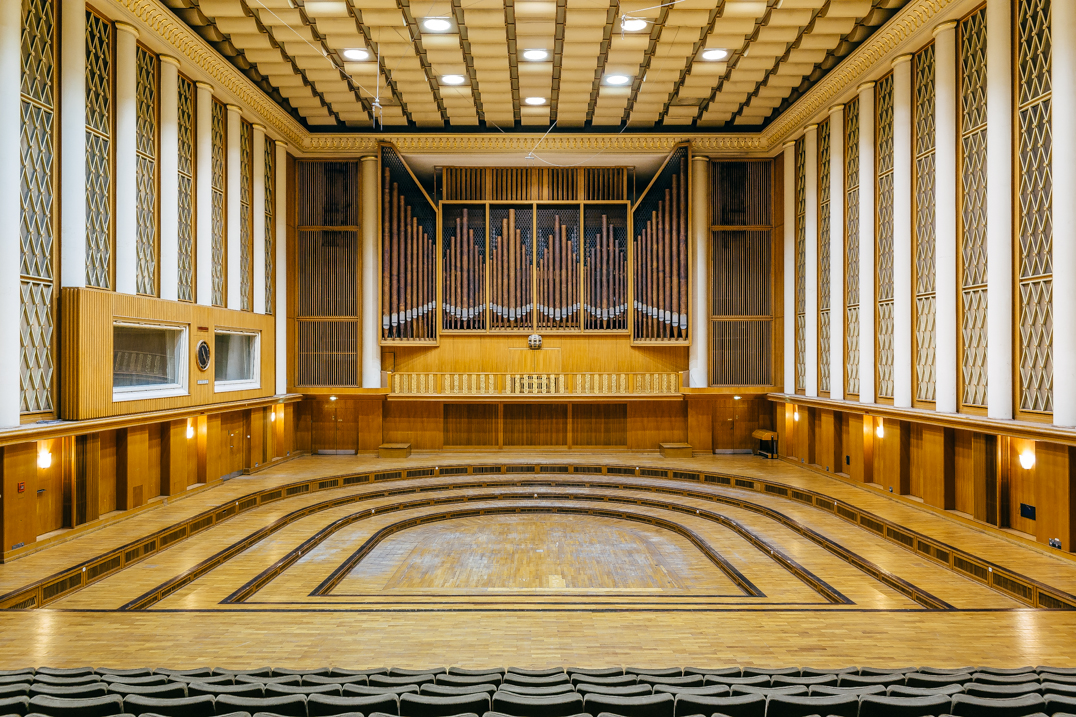
In the first case, studio rooms would need to be precisely designed for the desired reverberation time and characteristics. Various rooms would be used for different instruments recording. For example, a chamber hall has a long reverberation time; therefore, an orchestra recording sounds more natural compared of multiple takes of individual instruments inside small rooms with short reverberation time. A majestic architectural and historical example of this is the Funkhaus Nalepastraße in Berlin[1].
Instead, when specialized reverberating environments such as echo chambers were used (like in US Patent 2,431,962A [2]), the effect became a creative tool that departed from the simple idea of being a mere intrinsic characteristic of the recording ambient. A speaker would play the input sound, called dry, while microphones placed in various points around the space would record the resulting wet output. By changing the room characteristics (space dimension, materials, presence of reflectors) different sonic characteristics could be achieved.
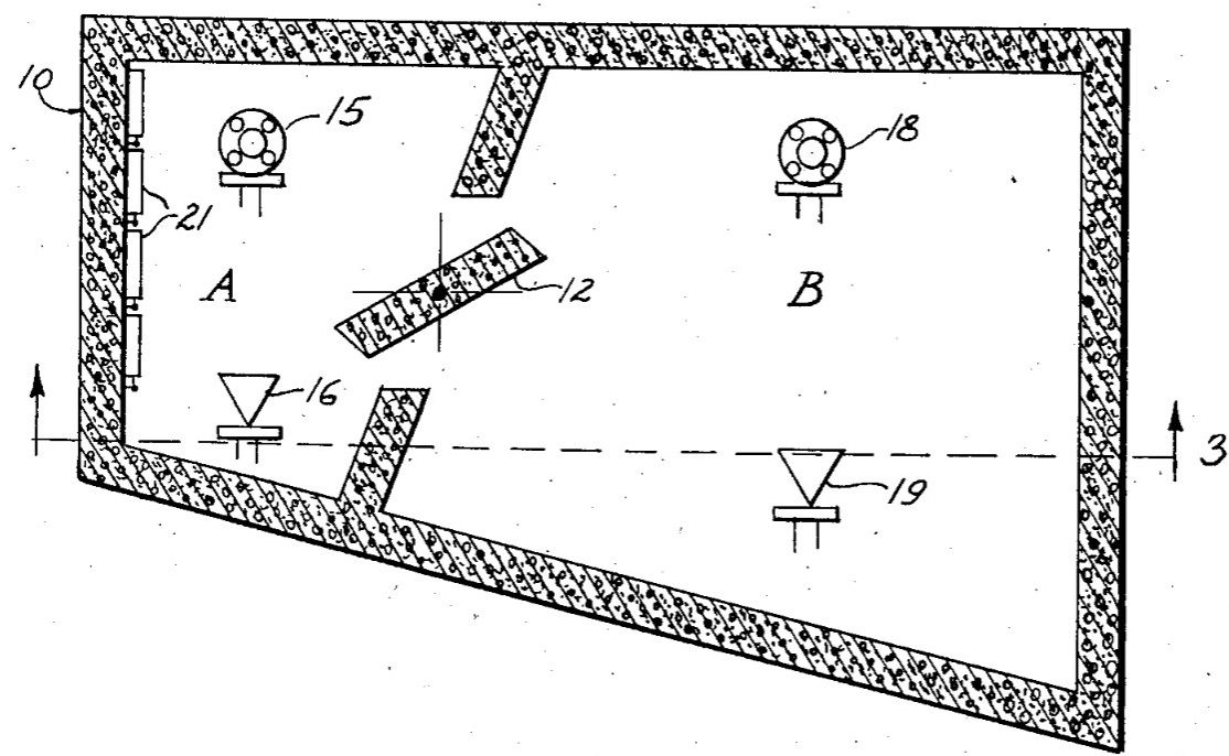
For example, in Figure 2, number 12 is a wall section able to rotate around a vertical axis, allowing the user to separate or connect the two sub echo chambers. number 16, 19 and 15, 18 are the speakers and microphones, respectively.
The most famous echo chamber is most probably the “Studio Two Echo Chamber” that Abbey Road Studios used in an infinite amount of records during the 50s. Among those, John Lennon’s vocal for A Day in the Life[3]. Before that, one of the first examples of the creative use of echo chambers in pop records is Peg O’ My Heart by The Harmonicats, published in 1947[4]. Ironically, the studio bathroom was used instead.
Plates
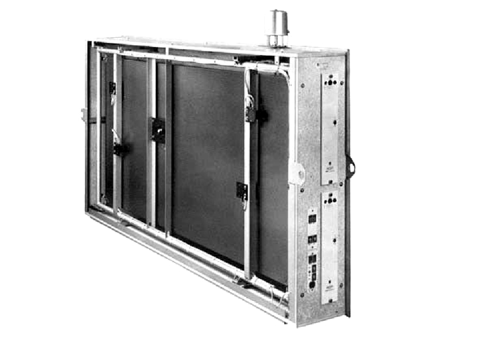
Because a specialized echo room meant leaving costly studio space unused (hence the use of the bathroom by the Harmonicats) the need for small, controlled reverberation environments quickly arose. To solve this, the famous EMT 140, commercialized by the German company EMT (US Patent 2,923,369A [6]), replaced an entire echo room with just 270 kilograms of a lightweight studio reverberation unit, shown in Figure 3. Commercialized in 1957, this 2.4 × 1.2 meter sheet of resonating steel used inductive drivers and pickup transducers for input and output, while the mechanical damper would ultimately control the reverberation time and the timbre of the reflections [5].
For the few ones who could afford it during the 60s, the EMT 140 became a staple in the most popular records, especially considering the extensive use by The Beatles in the Abbey Road studios starting from the very same year it was commercialized. On a technical note, its size, weight and sensitivity to external sounds requires that the unit needs to be placed in a quiet environment separated from the control room, typically in the basement. The Abbey Road Studios basement, in fact, houses the four iconic EMT 140s labeled A, B, C, and D.
Saddles
It’s hard to talk about artificial reverberation without bringing up spring reverbs. A few decades before the EMT 140, back in 1941, Laurens Hammond (yes, that Hammond) came up with a new “Electrical Musical Instrument” [8]. Hammond focused on faithfully emulating the sound of church organs, and because those were played in vast spaces such as cathedrals, mimicking the long reverb tails caused by many reflections in those environments was essential. To recreate that behavior, Hammond embedded springs in the reverberation units built into his organs. But to understand how springs can reproduce a reverb effect, we need to look at the source of Hammond’s inspiration.
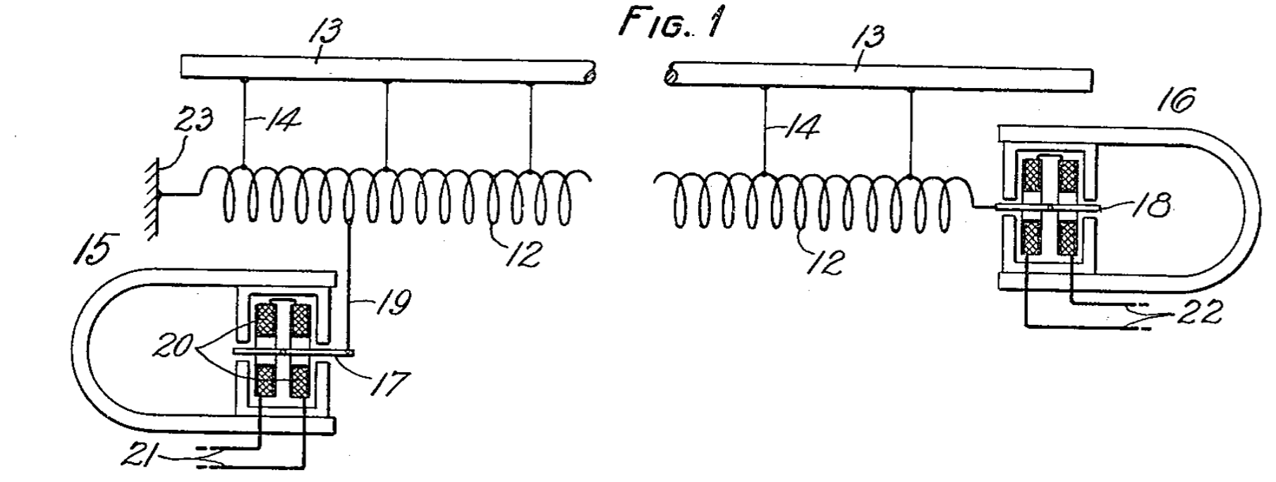
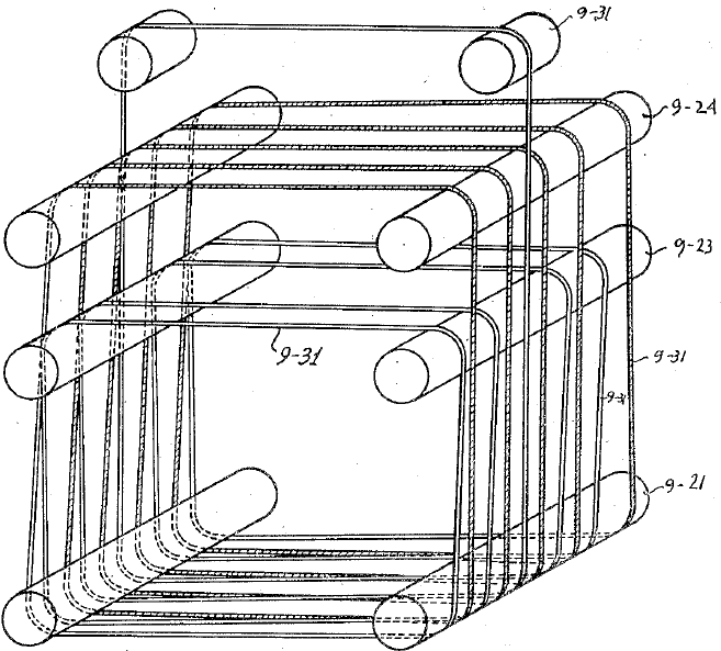
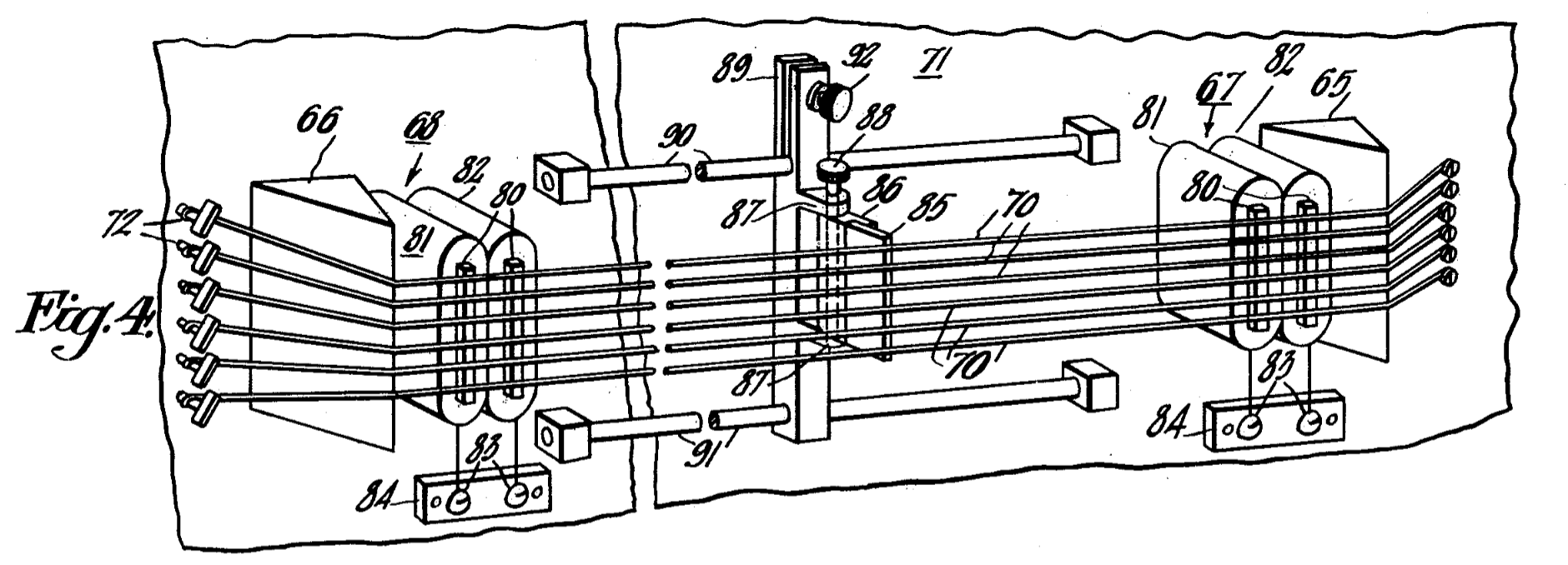
Online sources [9] suggest that the idea originated from a device patented in 1928 by Bell Labs for simulating the delay experienced on long-distance calls [7]. Figure 4 shows the structure of this device. An input signal is sent to an electromechanical transducer that excites a spring. The resulting wave travels through the spring and is captured at the opposite end by another transducer. The time it takes for the wave to move from one end to the other mimics the delay an electrical signal would experience when traveling through kilometers of telephone line. Unlike a telephone line, however, once the wave reached the end of the spring, it bounced back, producing a series of unwanted reflections. What seemed like a failure to the Bell Labs engineers turned out to be exactly what Laurens Hammond needed for his organs.
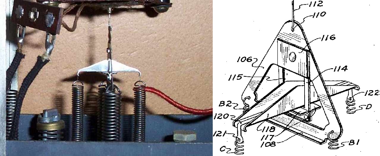
The first Hammond reverberation unit is often referred to as “The Saddle”[8]. It featured two primary springs responsible for generating the reverb effect, supported by four additional springs that helped to maintain balance. The support they were attached to resembled a saddle, hence the name (Figure 5). The primary springs were mounted vertically inside copper tubes partially filled with oil, a design that allowed the decay time to be adjusted by varying the amount of oil in each tube.
Necklaces
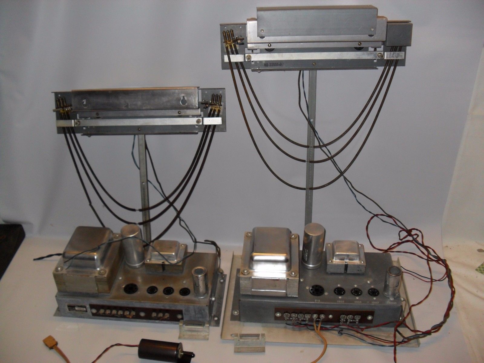
1958 saw a further development of the spring system. The impractical use of oil, which required the springs to be mounted exclusively in a vertical position, was abandoned in favor of a three-spring design. The springs were now mounted horizontally and fixed at both ends by transducers and left free at the center, resembling a “Necklace” because they hung in much the same way. This configuration is shown in U.S. Patent No. 2,982,819 by inventors H. E. Heinema and H. H. Canfield [12] (Figure 6). It was found that this implementation produced a more “natural” sound, closer to that of a real room.
Accurate Springs
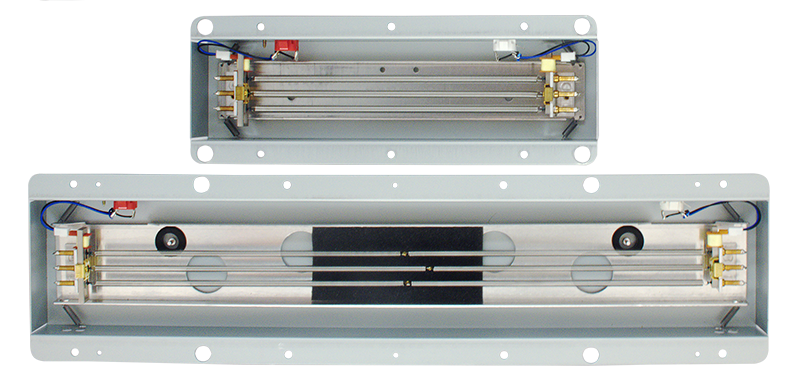
In 1961, Alan Young was asked to redesign the Necklace reverb to address the bumping problem. The original catenary shape was replaced with a straight configuration [13]. Greater attention was given to the specification of the springs: the new reverb tanks typically contained groups of two or three springs, each with a slightly different delay time to produce a more natural sound. The springs were attached at their ends with dampers, whose material determined the total reverberation time. In addition, they were enclosed in a rectangular, more compact metal tank that featured extra support springs to fully decouple external vibrations [14]. These units were marketed as the Accutronics (Hammond Organ Division) Type 4, a design that remains in production today (Figure 7).
After these developments, spring reverbs quickly became the staple of portable reverberation units. The main reason for this success is tied to Leo Fender, who installed the Type 4 in the Fender Twin Reverb (1962) and Fender Vibroverb (1963) guitar amplifiers, while standalone units such as the Fender 6G15 (also called the Fender Reverb Unit) were also released. Their compact size and low cost created a symbiotic relationship with the sound of the electric guitar itself. It’s hard to imagine a quick strum without the iconic boing.
Lines and Tapes
The principle of using delayed reflections to emulate reverberation can also be implemented through purely electrical means. Digital algorithms are of course the modern way to go, but let us still stick with analog systems. Traditionally, analog reverberation is achieved by converting an electrical signal into mechanical vibrations that propagate through springs or plates. However, delays can also be generated without leaving the electrical domain. Two main analog approaches have been explored over the years: transmission lines and magnetic tapes.
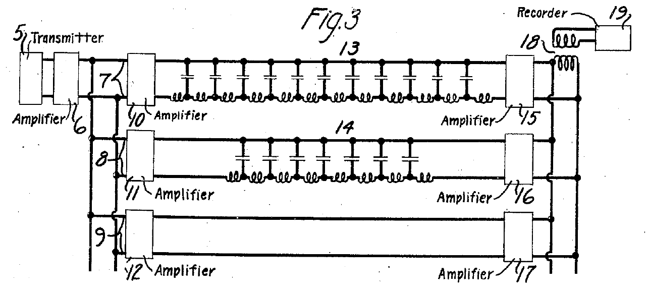
In 1924, J. Mills introduced a reverberation system based on transmission lines, as described in U.S. Patent No. 1,647,242 [16]. In essence, a transmission line acts as an electronic filter constructed from a ladder network of inductors and capacitors (Figure 9), which collectively produce a delay in the signal’s propagation. Mills’ system creates reverberation by mixing the original signal with a delayed version of itself through two such transmission lines, as shown in Figure 8. The two LC lines differ in their number of components: the longer line, containing more inductors and capacitors, produces a longer delay.
Multiple reflections can be achieved by introducing a feedback circuit, which is a technique later formalized in E. H. Schreiber’s 1932 U.S. Patent No. 1,947,621 [17]. However, the main limitation of this approach is that long delay times require many inductors, making the system bulky and expensive. To address this issue, S. J. Begun proposed an alternative in U.S. Patent No. 2,327,956, replacing the transmission-line delay network with an “infinite” magnetic tape loop (Figure 10) [18].
Buckets
About five decades later, Bucket Brigade Delay (BBD) integrated circuits were introduced, marking a major milestone in analog signal processing. One of the most notable examples was the Panasonic MN3011, consisting in a six-tap, 3328-stage BBD chip which became one of the first such devices used in commercial analog reverb pedals [19].
In these systems, a large analog shift register comprising thousands of stages was used to delay the incoming signal. Multiple outputs were taken from various points (taps) along the delay line, and the overall output was obtained by forming a weighted sum of these individual taps. The resulting signal could then be fed back into the input to create reflections. Conceptually, this approach echoed the same feedback principles described decades earlier by E. H. Schreiber [17].
Among the most famous pedals employing the MN3011 was the Morley Rock’n Verb, while Elektor Electronics published a DIY project about the MN3011 called “BBD Sound Effects Unit” in 1990 [20]. Bucked Brigade Delays are so popular that new chips are designed even today, such as the Sound Semiconductor SSI2100 [21].
Other Patents I did not mention
Tens of patents about analog reverberation systems exist. Here are some of them that I did not mention in the article:- U.S. Patent No. 2,600,870 - Synthetic Reverberation System by J. L. Hathaway and J. G. Petit (1947) [22]. This reverberation system used a set of strings stretched over a board (Figure 11). Its sound should be more similar to the one of a resonating guitar body rather than a proper reverb. Various examples of similar techniques are also employed in live electronics pieces that transform a piano into a resonating apparatus.
- U.S. Patent No. 2,768,235 - Reverberation Devices by A. F. Knoblaugh (1950) [23]. This is a rather weirdly arranged speaker-spring-microphone system (Figure 12).
- U.S. Patent No. 2,986,228A - Miniature Eco Chamber System by M. Rettinger and Carl N. Shipman Jr. (1961) [24]. This patent describes a miniature echo chamber that should be able to reproduce the same reverberation of a normal one.
Bibliography
[1] https://daily.redbullmusicacademy.com/2018/09/gerhard-steinke-funkhaus-berlin-sound-technology
[2] Michael Rettinger. Reverberation Method and System. US Patent 2,431,962A. Dec. 1947. https://patents.google.com/patent/US2431962A/
[3] https://www.abbeyroad.com/news/studio-two-echo-chamber-gearthatmadeus-3114
[4] https://www.youtube.com/watch?v=9BIuX7IsdE8
[5] https://www.barryrudolph.com/recall/manuals/emt140.pdf
[6] Walter K. Kuhl. Acoustic reverberation arrangements. US Patent 2,923,369A. June 1956. https://patents.google.com/patent/US2923369A/
[7] Raymond L. Wegel. Wave transmission device. US Patent 1,852,795. Apr. 1932. https://patents.google.com/patent/US1852795A
[8] Laurens Hammond. Electrical musical instrument. US Patent 2,230,836. Feb. 1941. https://patents.google.com/patent/US2230836A
[9] http://www.accutronicsreverb.com/pages/history.php
[10] https://www.hammondclub.nl/nl/menu/Hammond/De-Hammond-Encyclopedie/Reverb-history
[11] https://www.thegearpage.net/board/index.php?threads/worst-reverb.2007625/page-8
[12] Herbert E. Meinema & Herbert H. Canfield. Artificial reverberation apparatus. US Patent 2,982,819. May 1962. https://patents.google.com/patent/US2982819A/
[13] Alan C. Young. Artificial reverberation unit. US Patent 3,106,610. Oct. 1961. https://patents.google.com/patent/US3106610A/
[14] William C. Laube Jr. Reverberation unit having vibration-isolating suspension. US Patent 3,286,204. Apr. 1962. https://patents.google.com/patent/US3286204A/
[15] https://www.amplifiedparts.com/tech-articles/spring-reverb-tanks-explained-and-compared
[16] J. Mills. Recording and reproduction system. US Patent 1,647,242. Apr. 1924. https://patents.google.com/patent/US1647242A/
[17] Ernst H. Schreiber. Reverberation circuit. US Patent 1,947,621. Feb. 1934. https://patents.google.com/patent/US1947621A/
[18] Semi Joseph Begun. Magnetic recording and reproducing. US Patent 2,327,956A. Dec. 1940. https://patents.google.com/patent/US2327956A/
[19] https://www.experimentalistsanonymous.com/diy/Datasheets/MN3011.pdf
[20] https://worldradiohistory.com/UK/Elektor/90s/Elektor-1990-04.pdf
[21] https://www.soundsemiconductor.com/downloads/ssi2100datasheet.pdf
[22] Joseph G. Petit & Jarrett L. Hathaway. Synthetic reverberation system. US Patent 2,600,870A. Feb. 1947. https://patents.google.com/patent/US2600870A/
[23] Armand F. Knoblaugh. Reverberation devices. US Patent 2,768,235A. Oct. 1950. https://patents.google.com/patent/US2768235A/
[24] Michael Rettinger & Carl N. Shipman Jr. Miniature Reverberation Chamber System. US Patent 2,986,228A. May 1961. https://patents.google.com/patent/US2986228A/